
Industry news|2022-05-26| admin
Planetary gearbox is widely used in many industries. Compared with gear gearbox, planetary gearbox has better gear meshing accuracy, high precision, low noise during operation, small overall size, suitable for various working environments, and flexible in narrow working environments. to install. What is the internal structure of the planetary gearbox, the principle structure of the gearbox, let's follow the diagram to understand
The main transmission structures are planetary gear, sun gear and inner gear. Planetary gear deceleration is the principle of gear deceleration. There is a gear with a fixed axis position called the center gear or sun gear, and there is a gear with a variable axis on the side of the sun gear. The gear that rotates and revolves is called a planetary gear, and the planetary gear has a supporting member. It is called a planetary carrier, and the power is transmitted to the shaft through the planetary carrier, and then to other gears. They consist of a set of several gears forming a gear train. There is only one prime mover, and this epicyclic gear train is called a planetary gear train. Planetary gearbox is a kind of servo gearbox. Let's analyze the internal structure diagram and operation principle of planetary gearbox.
The planetary gearbox is a mechanical transmission component that connects the servo motor and the applied load in the motion control system. The functions of planetary gearbox in the operation control system of mechanical equipment mainly include: transmission of motor power and torque; transmission and matching of power speed; adjustment of inertia matching between the mechanical load on the application side and the motor on the drive side;
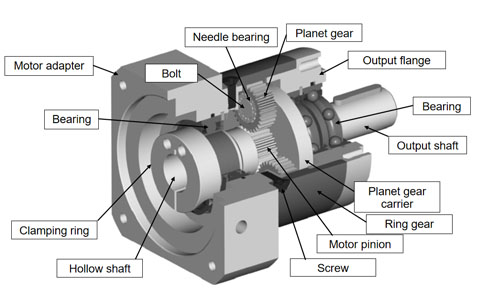
Internal structure diagram of planetary gearbox
It can be seen that in the structure of the planetary gear set, there are a plurality of gears surrounding a central gear along the inner ring of the gearbox housing, and when the planetary gearbox is running, with the rotation of the central gear, several gears around the periphery. The gears also "revolve" together around the central gear. Because the layout of the core transmission part is very similar to the way the planets in the solar system revolve around the sun, this type of gearbox is called a "planetary gearbox". The sun gear is often referred to as the "sun gear" and is driven to rotate by the input servo motor through the input shaft.
The internal structure of the planetary gearbox has a number of gears that rotate around the sun gear, called "planetary gears". The torque power is transmitted from the input shaft through the sun gear, and the power is transmitted to the load end through the output shaft. During normal operation, the orbit of the planetary gear "revolving" around the sun gear is the annular ring gear on the inner wall of the gearbox housing.
When the sun gear rotates under the drive of the servo motor, the engagement with the planetary gear causes the planetary gear to rotate; at the same time, due to the engagement of the other side of the planetary gear with the annular inner gear on the inner wall of the gearbox housing, finally Under the action of the rotation driving force, the planetary gear will roll on the annular ring gear in the same direction as the sun gear rotates, forming a "revolutionary" motion around the sun gear. Usually, each planetary gearbox will have multiple planetary gears, which will rotate around the central sun gear at the same time under the action of the input shaft and the rotational driving force of the sun gear to jointly undertake and transmit the output power of the gearbox.
It is not difficult to see that the input speed of the motor side of the planetary gearbox (that is, the speed of the sun gear) is higher than the output speed of its load side (that is, the speed of the planetary gear revolving around the sun gear), which is why it is called. The reason for the "gearbox".
The speed ratio between the drive side of the motor and the output side of the application is called the reduction ratio of the planetary gearbox, referred to as "speed ratio", which is usually represented by the letter "i" in the product specification, which is composed of the annular ring gear and the sun gear. is determined by the ratio of the dimensions (circumference or number of teeth). In general, the speed ratio of a planetary gearbox with a single-stage reduction gear set is usually between 3 and 10; a planetary gearbox with a speed ratio of more than 10 needs to use a two-stage (or more) planetary gear set for deceleration.
Like all motion control transmission mechanisms, when using planetary gearboxs in motion control equipment, its transmission efficiency, rigidity and precision also need to be considered. Due to the large number of meshing teeth during operation, the overall contact area of gear meshing is also relatively large. Therefore, compared with ordinary fixed gear gearboxs, planetary gearboxs have higher power transmission efficiency and stronger torque power output. capacity, while its transmission rigidity is also stiffer. Usually, the transmission efficiency of the servo planetary gearbox can reach more than 97%, the backlash is generally lower than 3arcmin, and the rigidity can reach 3Nm/arcmin or even higher.
Operation principle of planetary gearbox (illustration)

(1) The ring gear is fixed, the sun gear is active, and the planet carrier is passive.
It can be seen from the demonstration that this combination is a reduced speed transmission, usually the transmission ratio is generally 2.5 to 5, and the steering is the same.

(2) The ring gear is fixed, the planet carrier is active, and the sun gear is passive.
It can be seen from the demonstration that this combination is a speed-up transmission, the transmission ratio is generally 0.2 to 0.4, and the steering is the same.

(3) The sun gear is fixed, the ring gear is active, and the planet carrier is passive.
It can be seen from the demonstration that this combination is a deceleration transmission, the transmission ratio is generally 1.25 to 1.67, and the steering is the same.

(4) The sun gear is fixed, the planet carrier is active, and the ring gear is passive.
It can be seen from the demonstration that this combination is a speed-up transmission, the transmission ratio is generally 0.6 to 0.8, and the steering is the same.

(5) The planet carrier is fixed, the sun gear is active, and the ring gear is passive.
It can be seen from the demonstration that this combination is a deceleration transmission, the transmission ratio is generally 1.5 to 4, and the steering is reversed.

(6) The planet carrier is fixed, the ring gear is active, and the sun gear is passive.
It can be seen from the demonstration that this combination is a speed-up transmission, the transmission ratio is generally 0.25 to 0.67, and the steering is opposite.
(7) The case of combining any two elements of the three elements into one:
When the planet carrier and the ring gear are combined as the active part, the sun gear is the passive part, or the sun gear and the planet carrier are combined as the active part, and the ring gear is used as the passive part.
From the demonstration, we can see that there is no relative motion between the planetary gears, operating as a whole, the transmission ratio is 1, and the steering is the same. This combination is often used in automobiles to form a direct gear.
8) Any one of the three elements is active, and the other two elements are free:
It can be seen from the analysis that the other two components have no definite rotational speed output. The sixth combination method, due to the large acceleration, the steering of the active and passive parts is opposite, and this combination is usually not used in automobiles. The remaining seven combinations are more commonly used.